Modifying the i1i0 table
for the i1pro2
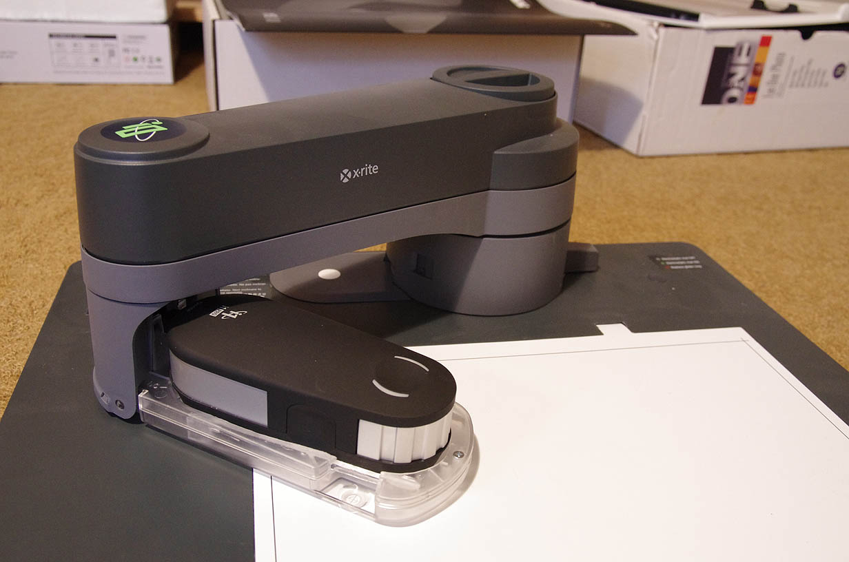
The X-Rite i1pro 2 is
backwards compatible in most ways with the original i1pro
spectrometer,
with the basic dimensions, aperture hardware, and driver being very
compatible. One area where
it is subtly different is in working with existing i1i0 tables. The
body of the i1pro2 is a little
lower, the foot is continuous rather than having a gap, the sides
are straighter, and the head a little
larger in diameter. Given the form fitting cradle in the i1i0, the
end result is that the i1pro2 won't
fit into an existing i1i0.
X-Rite has a scheme to allow existing i1i0's to be upgraded:
<http://www.xrite.com/product_overview.aspx?ID=1959>,
but for some of us not in North America, or who have not paid the
local distributor an outrageous price margin
for the privilege of buying it via them, this is not such an
attractive proposition.
Since It seems to be a simple mechanical issue, I thought I'd see
about modifying an existing i1i0 to solve this problem.
What follows is the result.
WARNING: This is not for the
feint of heart. If you are not the sort of person who has the
experience
and confidence in your ability to carry out changes that involve
carving away parts of an expensive piece
of kit and returning it to working order, don't attempt to emulate
what follows. Read it for entertainment
value only. It will void you warranty. You have been warned!
Removal
The first step is to remove the transparent foot. First detach the
arm from the main plate in the usual way,
and turn it over. Next remove the grey half-circle cover plate -
there is a small opening at the peak of the
circle to release the clip, or you could gently lever it from from
the ends. Next step is release the foot from its main
pivots, being careful not to tug it too far, since there is a cable
attached, and watch out for the counter-weight
rod and spring. The last step is to release the plug and cable, but
this needs to be done carefully so as not
to put too much tension on the spring, or you will break it's anchor
point (I found this out the hard way).
With the tension released, the spring can be detached from the foot.
The foot is in two pieces, an upper and lower, and is joined in
three places, two hooks at the rear,
and an internal molded clip at the front. You probably want to
remove the glide and its metal retaining clip, the clip
needing the small spring unwound in order to release it. The
internal molded clip is very hard to release, even though
you can get to it from the inside. It needs to be pushed outwards,
but since it is going to be discarded anyway,
the best approach is probably to work it until it snaps off
internally. This is because the two pieces are
going to have to be fitted together many times, and the clip will no
longer be a practical fastener.
Destruction
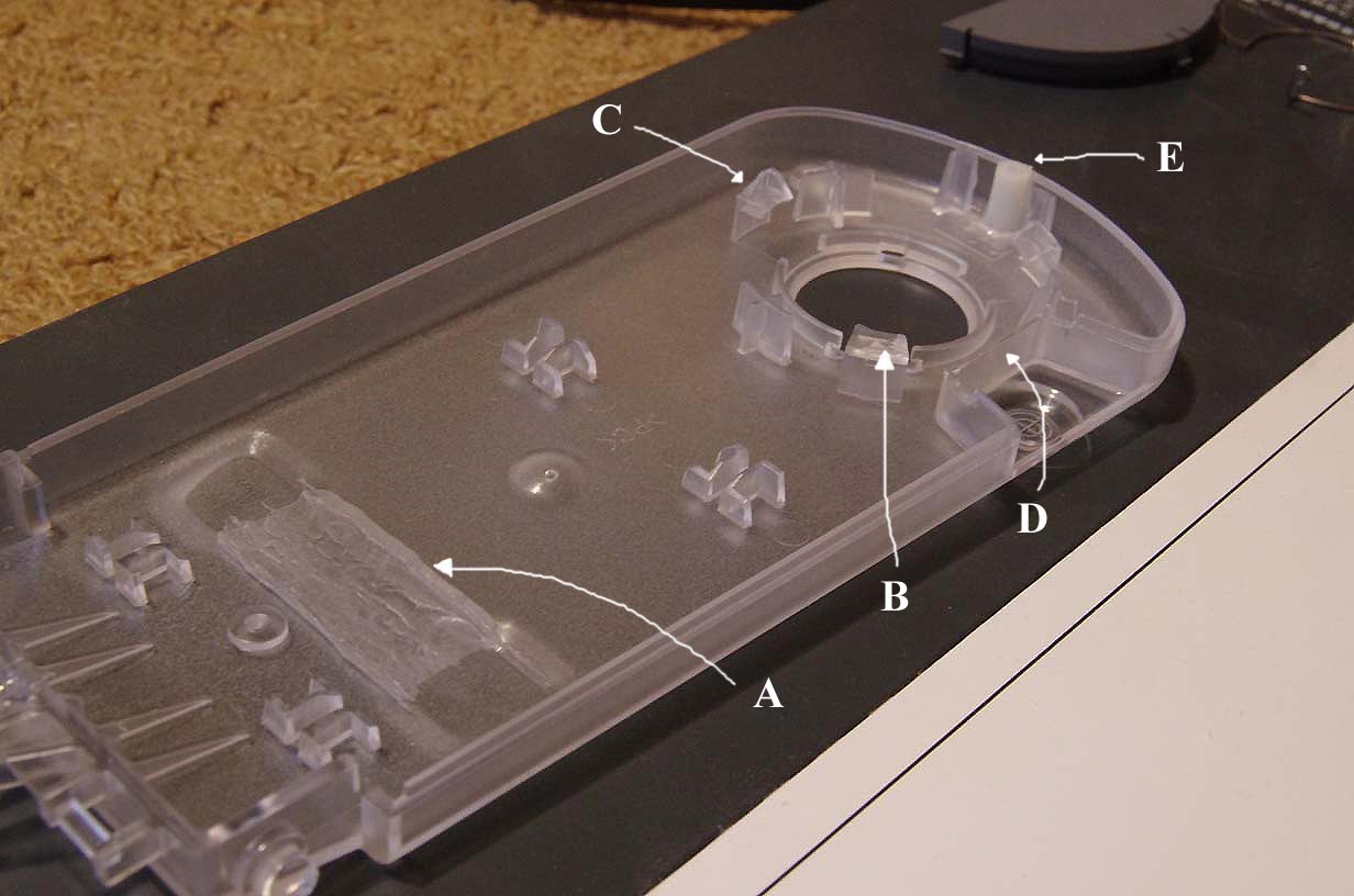
The bottom plate needs some subtle but careful modifications. One is
to extend the two depressions at the
heel of the instrument so that they join. (see "A") It doesn't have
to be exactly the same level, but within
a 0.1 mm or so of it. One approach would be to use a drill stand
that can be locked off in combination with
a small milling or cutting tool. The tool can be held at a fixed
spacing while the plate is slid one way and the other.
You want to avoid touching the existing depression surfaces, as they
establish the instrument level.
I used a high speed hand held rotary tool, and a variety of
attachments (such as a small
cutter, larger cutter, cutting wheel etc.) to perform the
modifications to the foot.
There are thee clips on the bottom plate that hold the aperture ring
in position, and two of them
need a slight modification. (The official X-Rite i1pro2 foot seems
to have a more sophisticated
locking arrangement than this.) The one at the 5 O'clock position
needs the sloping guide on the top of
it removing completely (see "B"), while the one at the 9 O'clock
position needs it half
removing (see "C"). This is to allow for the body of the instrument
having less clearance
in these areas. The cut-out for the visual location guide also needs
shaving slightly, to accommodate the
lower body of the instrument (see "D"), and laying the instrument
into position will act as a guide as
to how much to remove, and making sure that the instrument now clips
properly into position.
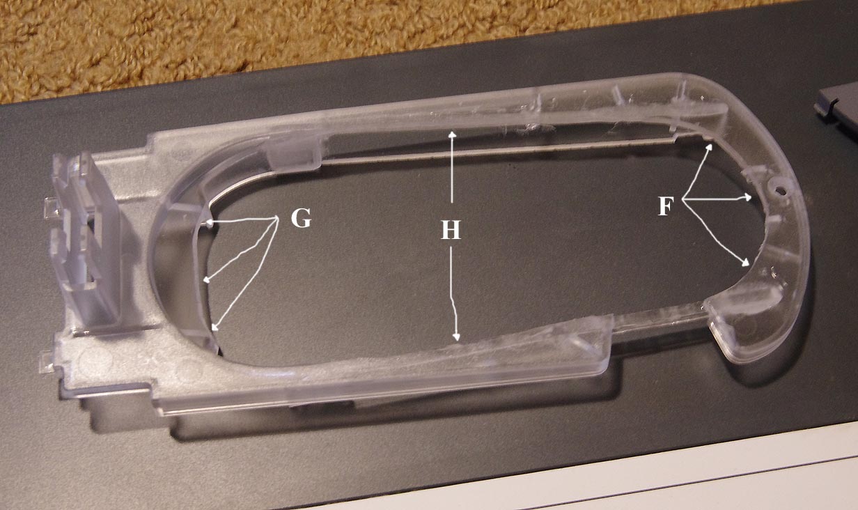
The upper plate needs much more extensive modifications.The half
circle at the head end needs
expanding in radius by 2-3mm (see "F"), while the heel needs carving
away to join the two wells
allowed for the i1pro foot. (see "G") Two straight cuts are needed
from the heel half circle to the
head half circle (see H). A great deal of ribbing will be cut away,
and the cut-out for the location
guide will become completely detached (the connection remaining in
the above photo is a new
bridging rib - see below). Once again, the instrument can be used as
a guide
as to how much to carve away. You're done when you can clip the
instrument into
the combined upper and lower plates, with a minimal amount of extra
clearance or slop around it.
Reconstruction
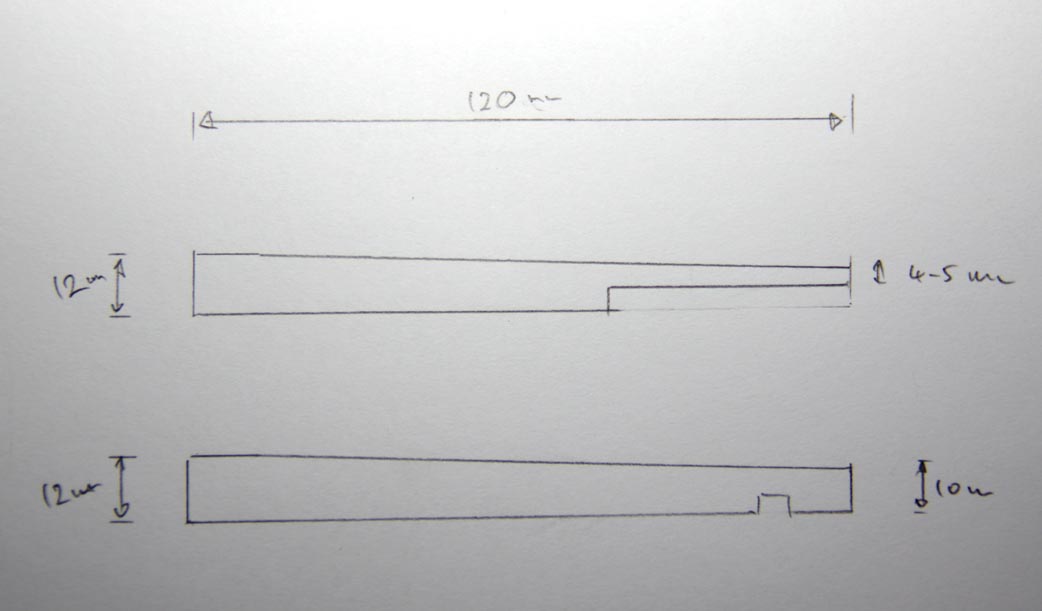
The upper plate will have been severely weakened in this whole
process, and now needs
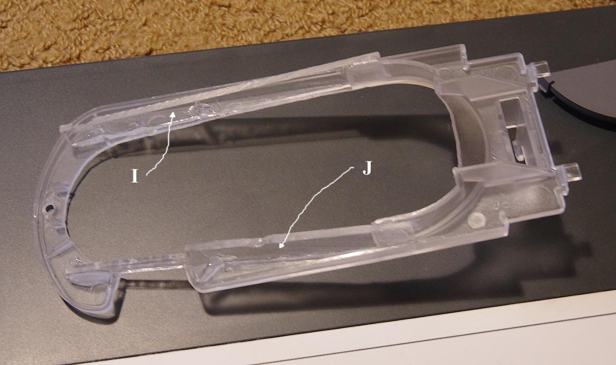
strengthening. I cut two new ribs out of a piece of 2.5mm thick
clear acrylic, both
120 mm long and 12mm wide tapering to 10mm. One needs a cut-out to
allow
for a molding bump (see "I" below), and the other needs thinning to
5mm where it crosses
the location guide cut-out (see "J"). Some finessing is also needed
where they sit beside
the remaining main ribs at the foot. There is about a 10mm overlap
that will be glued and
used to project the foot support out to the top plate. Room needs to
be cleared
for these new ribs along their length, and the plastic prepared for
gluing by
roughening the surfaces where they will be making contact.
I cut down and shaped a 2.5mm threaded plastic spacer for the bottom
plate (see "E"
in the first photo), to use with a matching countersunk screw in the
top plate to take the place
of the original molded internal clip that fastens the two plates
together.
It's important to make sure that everything fits together again,
before moving to the next step
of gluing the new pieces into the top plate.
The new ribs are glued into place using a two part clear epoxy glue,
laying it upside-down to do this,
so that the bottom plate can be used to align the separated pieces
around the location guide. The 10mm
glued overlap at the heel is important in returning strength to the
top plate.
Re-assembly is the reverse of the disassemble.
You can then double check that the i1pro2 clips into the modified
i1i0.
The completed
modifications, ready for testing.
Hopefully you've found this article informative and/or entertaining.
Graeme Gill.